Latest computing devices like smart-phones, tablets, notebooks, etc. require proper management of display backlighting to minimize power consumption and to make it easier for the user to view the display content under any ambient light conditions comfortably. The backlight control function system consists of three parts:
- Light sensor
- Backlight driver &
- Illumination calculation algorithm
In the present mobile or computing scenario, the backlight response w.r.t ambient light is controlled by the application processor, which requires a continuous digital signal to the light driver. The system leads to the noise in visual effects such as flickering during transitions from one backlight power level to another. Therefore it leads to the immense pressure on the working processor and consumes more power.
This article discloses the technique for backlight power management in computing devices that objective is to provide smooth or noise free transitions in backlight intensity in response to any changes in ambient light by providing a significant means to overcome the processor load and thereby reducing the power consumption.
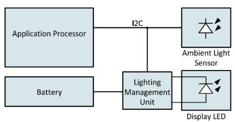
Figure 1: Architecture of a mobile display management system
As shown in Figure 1, The signal from an ambient light sensor or light is given to the application processor, and in response, the processor controls the lighting management unit (LED driver). This lighting management unit then drives the appropriate current to a string of backlight LEDs. This unit also controls other LEDs (viz. RGB event-indicator LEDs and a keypad backlight). The placement of the ambient light sensor is kept near the display and in the front side of the device, So that it becomes useful to calculate the illumination value using its algorithm and automatically compensates for the light absorption features of the glass of the display. This arrangement is beneficial for the reduction of power. Because if the light sensor is kept or mounted back to the dark glass of the system, It will require a high gain and less noise to calculate the correct illumination value.
In the present scenario, the display backlight problem makes it worse, whenever there is a minute change in ambient light, it will lead to a drastic change in the display intensity and due to this, the user may experience a distracting visual effect. The problem is again made even worse if the change is very momentarily and sharp from one backlight power level to another.
So the new technique for managing backlight power levels to overcome the said problem is introduced as when the display is turned on, the backlight value is set in response to the ambient light. The device might then change the backlight current one time only in response to a change in ambient light, and at second level the display backlight is then fixed irrespective of the ambient light changes. This phenomenon is to eliminate the risk of the backlight level oscillation in response to changes in ambient light inputs.
This technique is beneficial to make the display backlighting more responsive w.r.t. The ambient light without introducing the flicker and other distracting visual effects. In that the range of illumination values share the same backlight power input. It then adds the physical phenomenon to the implementation and filters/smooths the transitions from one power level to the other, and thereby reduces the burden on the applications processor.
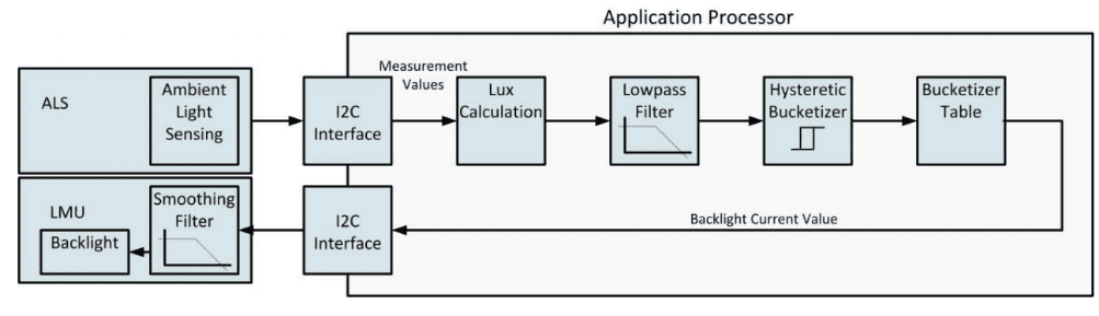
Figure 2: functional diagram of a circuit to provide smooth and flicker-free transitions between backlight power levels
As shown in figure 2 above, the application processor consists of various stages to provide the flicker free and smooth backlight transitions of the device. It incorporates the Low pass filter which is to slow down the system response to changes in illumination value given by the ambient light sensor or rather without LPF, the device might change the backlight power instantly in response to every change in ambient light. The ALS illumination value is the input value to the LPF and the noise-free or smooth illumination value from it.
Then it will give the output to the next stage, where the combination of the smoothing filter and a hysteresis added to the illumination value would prevent the backlight oscillation and save power as ambient light changes are reduced.
Pardeep Sharma